CABINET HARDWARE / THE ADJUSTABLE SHELF EDITION
Give every shelf
a place to land.
Lay out a paired set of cabinet sides. Keep the grid, skip the hardware, and take a clear hole map to the bench.
Build your hole map ↓Browser-local draft · No account · CSV / SVG / JSON
Your edits stay in this browser. Save a JSON backup to keep a separate copy.
Inside faces up · tops up · finished fronts outward
Available hole Full-width keep-out · fronts point outward
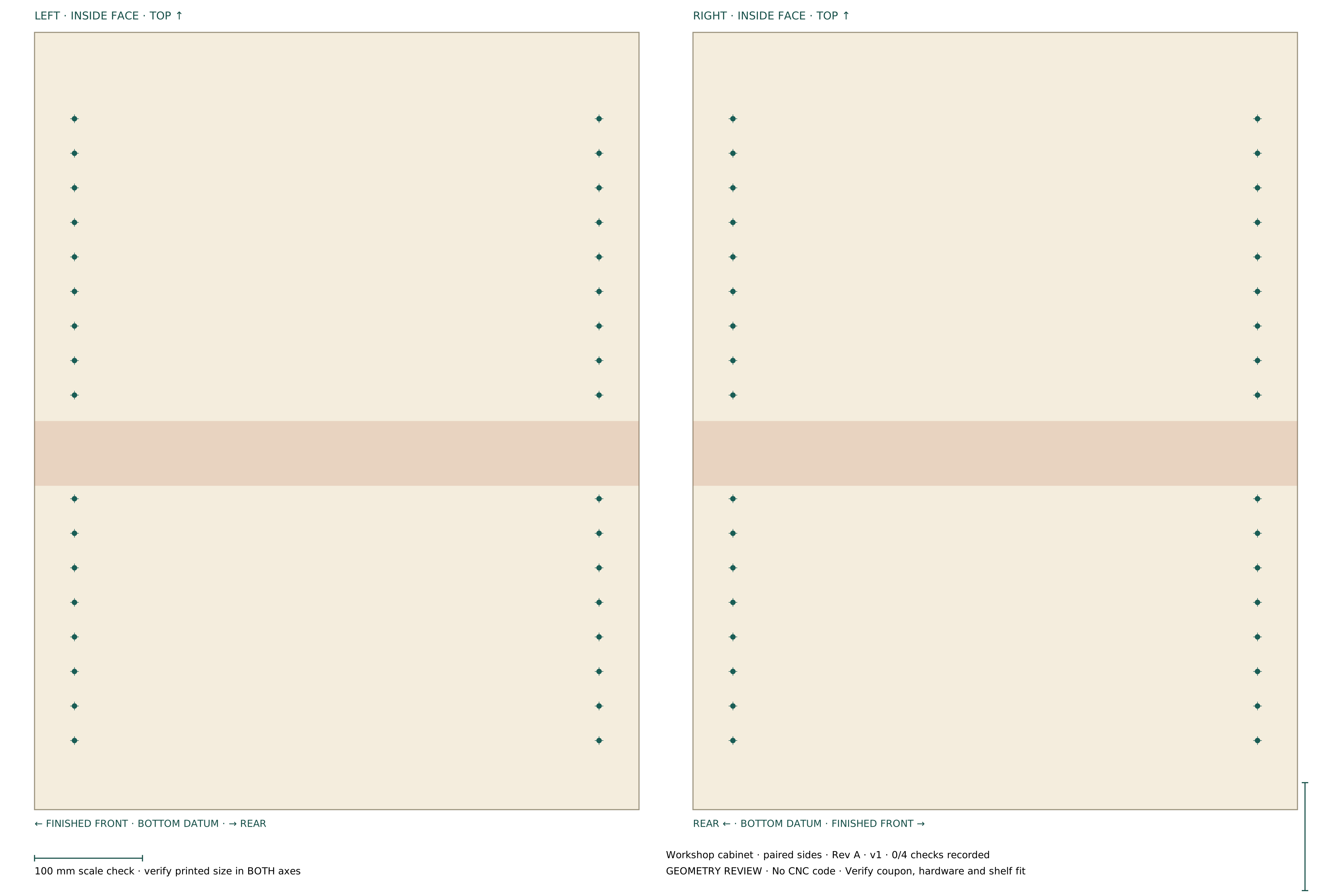
CSV: X from each panel’s finished front, Y up from its finished bottom. SVG: mirrored inside faces, physical mm size, two-axis scale marks. Check printer scaling. Read the transfer method ↗
Level register — choose a height to highlight it
BEFORE THE FIRST HOLE
One reference. Four matching supports.
Start with finished parts
Mark inside faces, finished fronts and the bottom datum on both equal-size side panels. Measure actual thickness. Changing an edge after drilling can move the reference. This planner models one left/right pair; shared dividers drilled from both faces need a separate review.
Reserve the occupied space
Record hinge, groove, fixing and support envelopes as measured height bands. The planner removes complete four-hole levels without shifting the original grid. A remaining level describes hole geometry; check the real shelf and door through their working travel.
Test the whole setup
Prove the bit, stop and actual pin in matching material. Compare low and high centers on the test pair, then install four supports and a shelf. A geometric pass cannot measure hole quality, case twist, shelf sag, support capacity or anchoring.
REPRODUCIBLE BENCH EXAMPLE
19 grid levels.
Two skipped. Seventeen remain.
The published example uses 720 × 560 × 18 mm sides, a 64 mm grid start, 32 mm pitch, 37 mm row setbacks and 5 mm holes. A measured-example band from 300 to 360 mm removes the 320 and 352 mm centers. The remaining 17 elevations produce 68 holes across the pair.
The 12 mm maximum tip penetration leaves 6 mm of modeled outer skin. The entered minimum is 3 mm. These are illustrative inputs, not drilling specifications for your hardware. All physical checks start unchecked.
THE COMPLETE FIELD GUIDE
From measured edge to fitted shelf.
Six focused methods cover the decisions a hole map cannot make for you. Each includes a worked review, a stop condition and a direct route back to your local draft.
Shelf Pin Spacing: Pitch, Start and Row Setbacks
Separate vertical hole pitch from front and rear setbacks, calculate the first usable level, and preserve a measured grid phase.
Read the method ↗FIELD GUIDE / 02Left and Right Shelf-Pin Panels: Keep the Datum
Label inside faces, finished fronts and bottom edges; read mirrored panel maps without reversing the drilling reference.
Read the method ↗FIELD GUIDE / 03Shelf Pin Hole Depth: Prove the Bit on a Test Piece
Distinguish drill-tip penetration, support engagement and remaining outer skin, then verify them in matching production material.
Read the method ↗FIELD GUIDE / 04Shelf Pin Keep-Outs Around Hinges, Backs and Joints
Translate measured hardware envelopes into shared exclusion bands while retaining the original shelf-pin grid.
Read the method ↗FIELD GUIDE / 05Continue a Shelf-Pin Row and Check a Printed Map
Verify a jig’s continuation against the original datum and use the SVG’s two-axis scale checks without assuming printer accuracy.
Read the method ↗FIELD GUIDE / 06Shelf-Pin Final Check: Four Supports and a Useful Record
Connect the hole map to actual support fit, shelf seating, cabinet squareness and a revision-controlled drilling record.
Read the method ↗METHOD / VERSION 1
Read the model before transferring the pattern.
For each nonnegative whole index n, the center height is origin + n × pitch. Accepted centers keep the full hole circle inside the entered top and bottom rim clearances. A keep-out removes a level if the circle touches or crosses its height interval. Every remaining level has two rows on each of two equal panels.
Front X equals the front setback; rear X equals panel depth minus rear setback. Coordinates in the CSV always use the panel’s own finished front and bottom. The right SVG panel is mirrored horizontally for a labeled inside-face bench view. Drill-tip reserve equals measured thickness minus entered maximum penetration. The model rejects overlapping rows, invalid dimensions, an insufficient reserve and a pattern with no complete remaining level.
All lengths use millimeters. Use the exact documented pitch: 1¼ inch converts to 31.75 mm and must not silently replace a 32 mm series. Kreg’s product documentation supports the example 32 mm pitch, 37 mm fence reference and matching pin/bit choice. True Position Tools provides an additional jig-specific reference sequence. Grid-phase arithmetic, mirrored display, full-width keep-outs and entered skin reserves are this planner’s stated model.
- Kreg KMA3232: 32 mm pitch, 37 mm fence setback and matching pins
- True Position Tools: shelf-pin drilling setup and reference holes
Sources checked 2026-10-15. By WoodCutTool editorial team.
Keep the record with the project
Dimensions, notes and evidence boxes stay in this browser’s local draft. If storage is unavailable, the current session still calculates and exports; the status explains the fallback. JSON import previews a replacement before applying it. Save a separate backup before clearing browser data. CSV and SVG describe your current geometry and evidence count; they are reference files and contain no machine drilling program.